Products
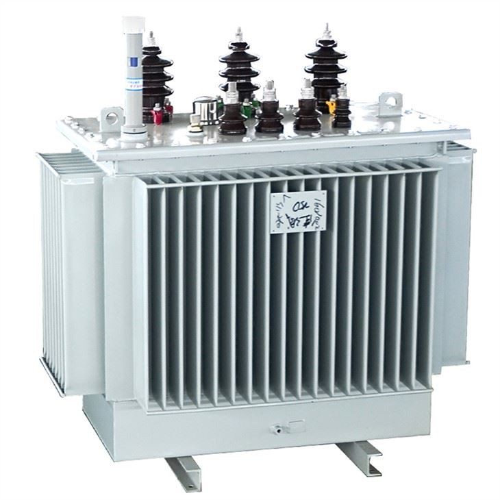

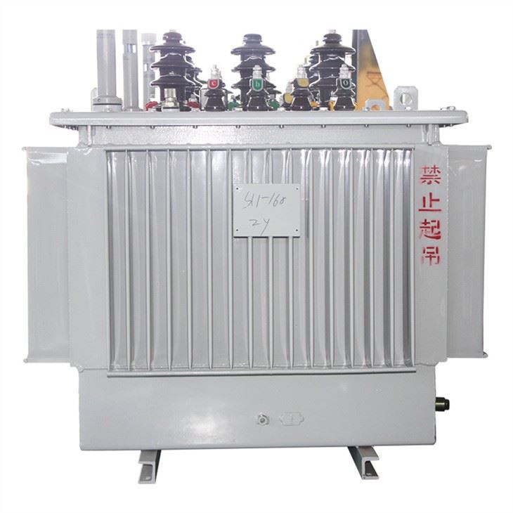
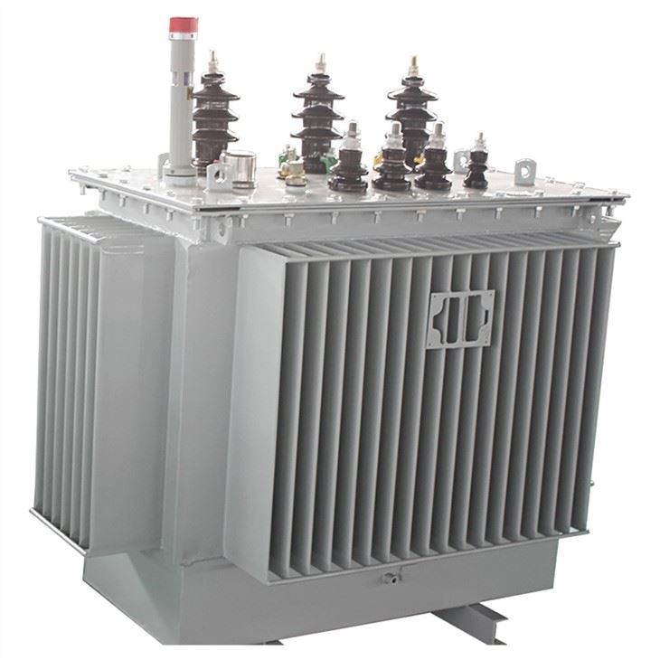
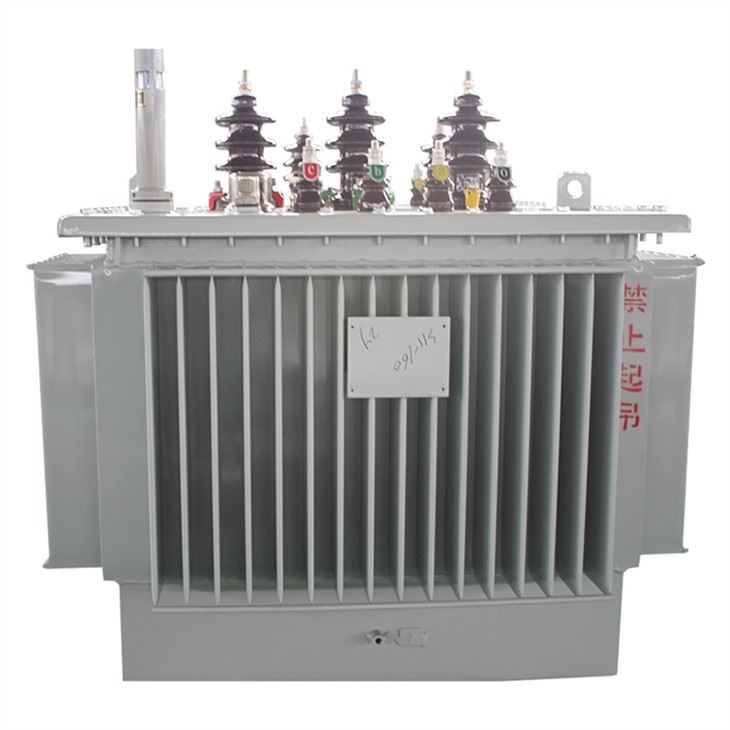
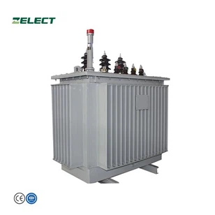
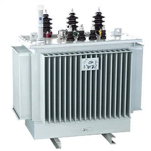
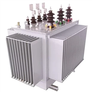
Indoor Oil Type Electrical Transformer
Rated Voltage: up to 36KV
Rated Capacity: up to 20 MVA
Can Customize as per your requirements
Features
Products Description
2-YEARS WARRANTY
Our sales manager Grace with 10-years distribution transformer exporter experience
Will Help You Make Technical Solutions and Shipment Solutions
Contact Grace Now!
Oil-immersed transformers are a vital component in the electrical distribution system, as they are used to transfer electrical energy from one circuit to another by means of electromagnetic induction. These transformers have a unique structure that allows them to work efficiently and reliably, even under extreme operating conditions.

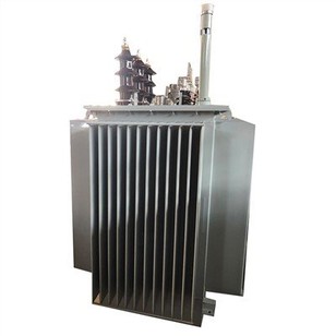
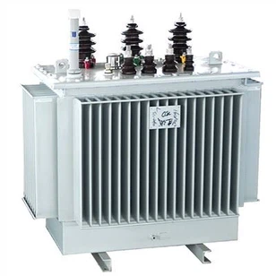
The structure of an oil-immersed transformer mainly comprises a core, winding, insulating materials, and an oil tank.
The core is made of high-quality magnetic steel sheets that are stacked together to form a column, which is then placed inside the oil tank.
The winding consists of a high-conductivity copper wire that is wrapped around the core, creating a magnetic field. The winding is sorted into two categories – primary winding and secondary winding. The primary winding is the input, and the secondary winding is the output.
Insulating materials are used to separate the windings and the core parts, thus preventing electrical breakdown. These materials must be able to handle the heat generated during the transformer's operation and must have good electrical and mechanical properties.
The oil tank contains the transformer oil, which is used as a coolant and an insulator. The oil helps to regulate the temperature of the transformer by dissipating the heat generated during the transformer's operation. It also acts as a dielectric insulator that prevents electrical breakdown in the transformer.
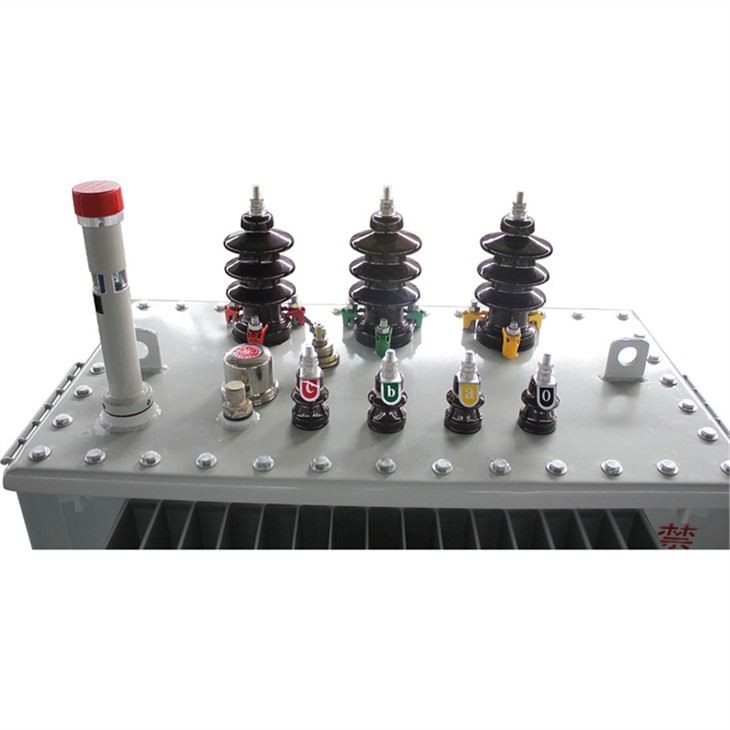
The conservator tank is used to control the oil level and to accommodate the expansion of the oil due to thermal effects.
The oil temperature gauge is used to measure the temperature of the transformer oil, which helps to determine the transformer's operating condition.
Products Parameter
Table 1: 6kV, 10kV & 30kVA-2500kVA Power Transformer With Off Circuit Tap Changer
| Rated Capacity (kVA) | Voltage Combination | Connection Group Symbol | No-load Loss R(W) | Load Loss R(W)75℃ | Impedance Voltage (%) | No-load Current(%) | ||
| High Voltage (KV) | Tapping Range of High Voltage | Low Voltage (KV) | ||||||
| 30 | 6 6.3 10 10.5 | ±5% ±2×2.5% | 0.4 | Dyn11 Yzn11 Yyn0 | 100 | 630/600 | 4 | 2.8 |
| 50 | 130 | 910/870 | 2.5 | |||||
| 63 | 150 | 1090/1040 | 2.4 | |||||
| 80 | 180 | 1310/1250 | 2.2 | |||||
| 100 | 200 | 1580/1500 | 2.1 | |||||
| 125 | 240 | 1890/1800 | 2 | |||||
| 160 | 280 | 2310/2200 | 1.9 | |||||
| 200 | 340 | 2730/2600 | 1.8 | |||||
| 250 | 400 | 3200/3050 | 1.7 | |||||
| 315 | 480 | 3830/3650 | 1.6 | |||||
| 400 | 570 | 4520/4300 | 1.5 | |||||
| 500 | 680 | 5410/5150 | 1.4 | |||||
| 630 | 810 | 6200 | 1.3 | |||||
| 800 | 980 | 7500 | 4.5 | 1.2 | ||||
| 1000 | 1150 | 10300 | 1.1 | |||||
| 1250 | 1360 | 12000 | 1 | |||||
| 1600 | 1640 | 14500 | 0.9 | |||||
| 2000 | 1940 | 18300 | 5 | 0.4 | ||||
| 2500 | 2290 | 21200 | 0.4 | |||||
Technical Parameter for S11 Series 20kV Power Transformer With Off Circuit Tap Changer
| (KVA)Rated capaci | Voltage Combination | Connection Group Symbol | No-load Loss(W) | Load Loss (W)75℃ | No-load Current (%) | Short-circuit Impedance(%) | ||
| High Voltage (KV) | Tapping ranges of High Voltage | Low Voltage(KV) | ||||||
| 30 | 20 | ±5% ±2×2.5% | 0.4 | Dyn11 Yzn11 Yyn0 | 100 | 690/660 | 2.1 | 5.5 |
| 50 | 130 | 1010/960 | 2 | |||||
| 63 | 150 | 1200/1150 | 1.9 | |||||
| 80 | 180 | 1440/1370 | 1.8 | |||||
| 100 | 200 | 1730/1650 | 1.6 | |||||
| 125 | 240 | 2080/1980 | 1.5 | |||||
| 160 | 290 | 2540/2420 | 1.4 | |||||
| 200 | 340 | 3000/2860 | 1.3 | |||||
| 250 | 400 | 3520/3350 | 1.2 | |||||
| 315 | 480 | 4210/4010 | 1.1 | |||||
| 400 | 570 | 4970/4730 | 1 | |||||
| 500 | 680 | 5940/5660 | 1 | |||||
| 630 | 810 | 6820 | 0.9 | 6 | ||||
| 800 | 980 | 8250 | 0.8 | |||||
| 1000 | 1150 | 11330 | 0.7 | |||||
| 1250 | 1380 | 13200 | 0.7 | |||||
| 1600 | 1660 | 15950 | 0.6 | |||||
| 2000 | 1950 | 19140 | 0.6 | |||||
| 2500 | 2340 | 22220 | 0.5 | |||||
Technical Parameter for S11 Series 35kV Power Transformer With Off Circuit Tap Changer
| Model | Voltage Combination | Connection Group Symbol | No-load Loss (W)75℃ | Load Loss R(W) | Impedance Voltage (%) | No-load Current(%) | ||
| High Voltage (kV) | Tapping Range of High Voltage% | Low Voltage (kV) | ||||||
| 50 | 35 38.5 | ±2×2.5% ±5% | 0.4 | Dyn11/ Yyn0 | 160 | 1200/1140 | 6.5 | 1.3 |
| 100 | 230 | 2010/1910 | 1.1 | |||||
| 125 | 270 | 2370/2260 | 1.1 | |||||
| 160 | 280 | 2820/2680 | 1 | |||||
| 200 | 340 | 3320/3160 | 1 | |||||
| 250 | 400 | 3950/3760 | 0.95 | |||||
| 315 | 480 | 4750/4530 | 0.95 | |||||
| 400 | 580 | 5740/5470 | 0.85 | |||||
| 500 | 680 | 6910/6580 | 0.85 | |||||
| 630 | 830 | 7860 | 0.65 | |||||
| 800 | 980 | 9400 | 0.65 | |||||
| 1000 | 1150 | 11500 | 0.65 | |||||
| 1250 | 1400 | 13900 | 0.6 | |||||
| 1600 | 1690 | 16600 | 0.6 | |||||
| 2000 | 1990 | 19700 | 0.55 | |||||
| 2500 | 2360 | 23200 | 0.55 | |||||
Testing
TIANWEI believes that quality means absolute congruity and compliance with customer's requirements and international standards.
Therefore, TIANWEI has equipped its testing lab with the most modern testing equipment and instrumentation devices to ensure conformity to the highest level of quality and safety, where every transformer produced by TIANWEI is tested according to IEC standards.
Routine Tests
1- Measurement of winding resistance
2- Measurement of voltage ratio and phase displacement
3- Measurement of short circuit impedance and load losses
4- Measurement of no-load losses and current
5- Dielectric routine tests
(separate source AC voltage withstand test and short duration induced over-voltage withstand test)
6- Measurement of insulation resistance
Type Tests
1- Temperature rise test according to IEC 60076-2
2- Lighting impulse test according to IEC 60076-3
Special Tests
1- Short circuit withstand test (as per IEC 60076-5)
2- Measurement of zero-sequence impedance(s) on three-phase transformers
3- Determination of sound levels (as per IEC 60076-10)
4- Measurement of the harmonics of the no-load current
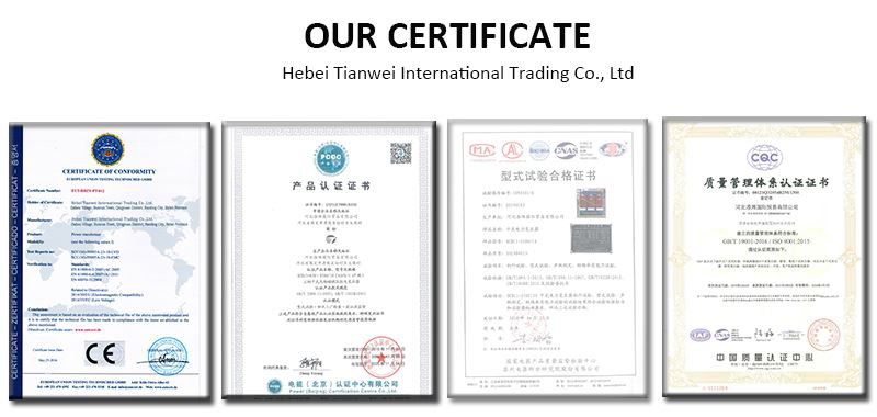
Our Certificate
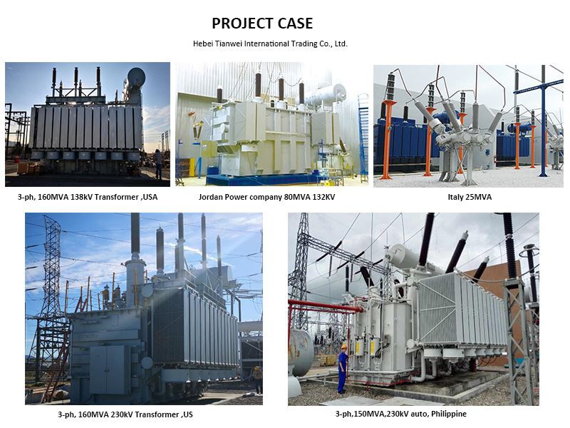
Project Case
Our Factory
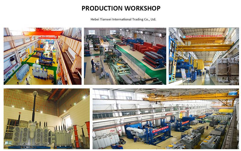
Our factory covers an area of 33,300 square meters, with a total construction area of 6,100 square meters. There are currently 260 employees, including 18 technicians who have been engaged in the research and development of transformer products for many years, and 8 high-quality corporate managers. With the expansion of production scale and the increase of product varieties, it has now developed into a high-tech innovative enterprise that annual production capacity of more than 1000MVA, integrating the design, production and sales of open-type dry-type transformers, epoxy resin cast dry-type transformers, amorphous alloy transformers, and special transformers.
Hot Tags: indoor oil type electrical transformer, China, suppliers, manufacturers, factory, buy, price, for sale, 3 phase electrical transformers, cooper 300 kva transformer, 2 mva 11kv transformer, 3 mva transformer, 2 5 mva transformer, utility transformer
You Might Also Like
 Learn More
Amorphous Alloy Distribution Power Substation Transf...
 Learn More
10KV Three Phase Oil Immersed Distribution Transformer
 Learn More
20KV Three Phase Oil Filled Distribution Transformer
 Learn More
3 Phase Oil Immersed Type Distribution Transformer
 Learn More
Oil Immersed Self Cooled Hermetically Sealed Type Tr...
 Learn More
3 Phase Oil Filled Self Cooled Type Transformer
Send Inquiry