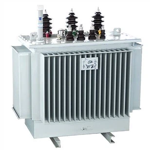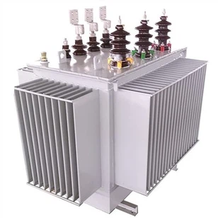
Three Dimensional Wound Iron Core Power Distribution Transformer
1. Product introduction:
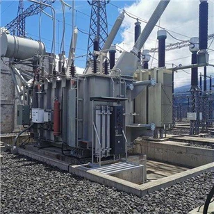
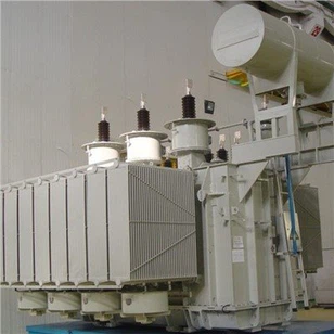
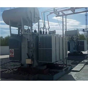
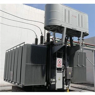
The body of the S13 series three-dimensional wound iron core power distribution transformer has a three-dimensional triangular shape as a whole. There are pull screws around and in the center. It is integrated with the upper and lower iron yoke insulation and laminated wood blocks. The high and low voltage coils are round and concentrically wound, which can effectively resist Axial and radial mechanical stress during sudden short-circuit, strong short-circuit resistance.
The iron core is made of cold-rolled silicon steel sheet, which has good stability, low noise, and low no-load loss. The coil is made of high-quality magnet wire and has low load loss.
Three-dimensional wound iron core transformers are currently implementing the standards: "Technical Parameters and Requirements for Three-phase Oil-immersed Three-dimensional Wound Iron Core Distribution Transformers" and "Three-phase Distribution Transformer Energy Efficiency Limits and Energy Efficiency Grades".

2. Product Features:
Low loss: According to the current international GB/T6451-1999 "Technical Parameters and Requirements of Three-Phase Oil-immersed Power Transformers", the capacity is 30-1600kVA, the no-load loss of S13-M.RL series is reduced by 50% on average, and the load loss is reduced by 30% on average;
Low no-load current: Due to the excellent material of the wound core and the characteristics of winding processing, the no-load current is significantly reduced. According to JB/T10088-1999 noise standard, the noise of S13-M.RL series is reduced by about 7-9dB.
Strong short-circuit resistance: The transformer body is in the shape of a three-dimensional triangular prism as a whole, with pulling screws all around and in the center, which are integrated with the upper and lower iron yoke insulation and laminated wood blocks, which can effectively resist the axial and radial mechanical stress.

Model | Rated Power(kVA) | No Load Loss(W) | On Load Loss(W) | No Load Current | Impedance Voltage |
S13-M.RL-30/10 | 30 | 80 | 600/630 | 0.34 | 4 |
S13-M.RL-50/10 | 50 | 100 | 870/910 | 0.28 | 4 |
S13-M.RL-63/10 | 63 | 110 | 1040/1090 | 0.26 | 4 |
S13-M.RL-80/10 | 80 | 130 | 1250/1310 | 0.25 | 4 |
S13--M.RL-100/10 | 100 | 150 | 1500/1580 | 0.24 | 4 |
S13--M.RL-125/10 | 125 | 170 | 1800/1890 | 0.23 | 4 |
S13--M.RL-160/10 | 160 | 200 | 2200/2310 | 0.21 | 4 |
S13--M.RL-200/10 | 200 | 240 | 2600/2730 | 0.2 | 4 |
S13--M.RL-250/10 | 250 | 290 | 3050/3200 | 0.19 | 4 |
S13--M.RL-315/10 | 315 | 340 | 3650/3830 | 0.18 | 4 |
S13--M.RL-400/10 | 400 | 410 | 4300/4520 | 0.17 | 4 |
S13--M.RL-500/10 | 500 | 480 | 5150/5410 | 0.15 | 4 |
S13--M.RL-630/10 | 630 | 570 | 6200 | 0.14 | 4.5 |
S13--M.RL-800/10 | 800 | 700 | 7500 | 0.13 | 4.5 |
S13--M.RL-1000/10 | 1000 | 830 | 10300 | 0.12 | 4.5 |
S13--M.RL-1250/10 | 1250 | 970 | 12000 | 0.11 | 4.5 |
S13--M.RL-1600/10 | 1600 | 1200 | 14500 | 0.1 | 4.5 |