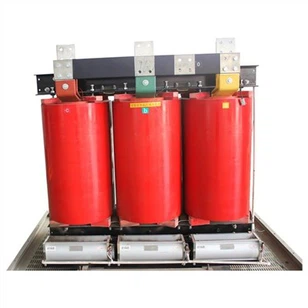
Three Phase Transformer Technical Parameters
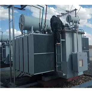
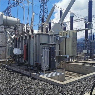
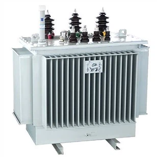
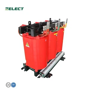
The three phase transformer is mainly a device that uses the principle of electromagnetic induction to change the AC voltage. The main components are the primary coil, the secondary coil and the iron core. The main functions include voltage conversion, current conversion, impedance conversion, isolation, voltage regulation (magnetic saturation transformer). In order to improve the understanding of transformers, transformer manufacturers share the technical parameters of transformers.
First, the main technical parameters of three phase transformer:
Under the specified operating environment and operating conditions of the transformer, the main technical data are generally marked on the nameplate of the transformer. Mainly include rated capacity, rated voltage, rated frequency, winding connection group, rated performance data (impedance voltage, no-load current, no-load loss and load loss) and total weight.
a. Rated capacity (kVA): rated voltage. The capacity that can be delivered when the rated current works continuously.
b. Rated voltage (kV): the working voltage that the transformer can withstand when it works for a long time. In order to meet the needs of grid voltage changes, the high-voltage side of the transformer has taps, and the output voltage of the low-voltage side is adjusted by adjusting the number of turns of the high-voltage winding.
c. Rated current (A): The current allowed by the transformer to pass for a long time under the rated capacity.
d. No-load loss (kW): the rated voltage at the rated frequency, applied to the terminals of one winding, the effective power absorbed when the remaining windings are turned on. It is related to the performance of the iron core silicon steel sheet, the manufacturing process and the applied voltage.
e. No-load current (%): When the three phase transformer is under rated voltage and no-load on the side, the current passing through the winding is usually expressed as a percentage of the rated current.
f. Load loss (kW): The secondary winding of the transformer is short-circuited, and the transformer manufacturer believes that the rated current is passed at the rated tap position of the primary winding, and the power consumed by the transformer at this time.
g. Impedance voltage (%): When the secondary winding of the transformer is short-circuited, the voltage is gradually increased from the primary winding, and the short-circuit current of the secondary winding is equal to the rated voltage applied to the primary side. Usually expressed as a percentage of rated voltage.
h, phase and frequency: the three-phase starting point is represented by s, and the single-phase starting point is represented by d. The Chinese national standard frequency f is 50Hz. There are 60Hz countries abroad (such as the United States).
I. Temperature rise and cooling: The temperature difference between the three phase transformer winding or upper oil temperature and the surrounding environment of the transformer is called the temperature rise of the winding or upper oil surface. The temperature rise limit of the oil-immersed transformer winding is 65K, and the oil surface temperature rises to 55K. There are also various cooling methods: oil self-cooling, forced air cooling, water cooling, tubes, chips, etc.
j. Insulation level: There are insulation grade standards. The insulation level is displayed as follows: the insulation level of the transformer with a high voltage rated voltage of 35kV and a low voltage rated voltage of 10kV is displayed as LI200AC85/LI75AC35. Among them, LI200 is a transformer with high voltage lightning impulse withstand voltage of 200kV, power frequency withstand voltage of 85kV, low voltage lightning impulse withstand voltage of 75kV, and power frequency withstand voltage of 35kV. At present, the insulation level of oil-immersed transformer products is LI75AC35, the high voltage lightning impulse withstand voltage of the transformer is 75kV, the power frequency withstand voltage is 35kV, and the low voltage is 400V, which can be ignored.
K. Connection group label: According to the phase relationship of the secondary winding, the transformer windings are connected to various combinations, which are called connection groups of windings. To distinguish between different groups of connections, clock notation is often used. That is to say, fix the amount of line voltage on the high-voltage side on the long needle of the clock and 12, and use the amount of line voltage on the low-voltage side as the short needle of the clock. If you see which number the short needle is, use it as the corresponding connection group.