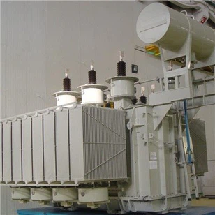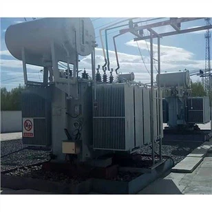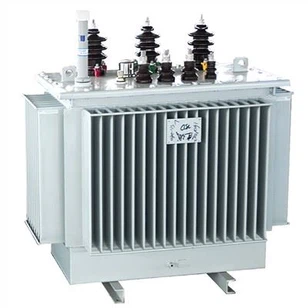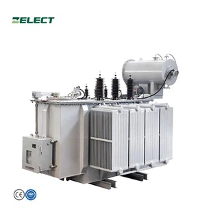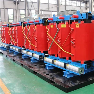
Basic Structure Of Single Phase Overhead Distribution Transformers
1. Iron core
The iron core constitutes the magnetic circuit system of the transformer and serves as the mechanical skeleton of the transformer. The iron core is composed of an iron core column and an iron yoke. The transformer winding is set on the iron core column, and the iron yoke is used to connect the iron core column to close the magnetic circuit. The requirements for the iron core are that the magnetic permeability is better, and the hysteresis loss and eddy current loss should be as small as possible, so they are all made of silicon steel sheets with a thickness of 0.35 mm. At present, domestic silicon steel sheets include hot-rolled silicon steel sheets, cold-rolled non-oriented silicon steel sheets, and cold-rolled grain-oriented silicon steel sheets. In the 1960s and 1970s, the power transformers produced in my country mainly used hot-rolled silicon steel sheets. Due to their large iron loss, the magnetic permeability was relatively poor, and the core stacking coefficient was low (because both sides of the silicon steel sheets were coated with insulating paint) , is no longer used. At present, domestic low-loss energy-saving transformers all use cold-rolled grain-oriented silicon steel sheets, which have low iron loss and high core stacking coefficient (because the surface of silicon steel sheets is insulated with oxide films, no need to apply insulating paint).
According to the structure of the transformer core, it can be divided into two categories: core transformer and shell transformer. Cardioid transformers are on both sides
The windings are placed on the iron core column to form a form in which the windings surround the iron core. Shell-type transformers place windings on the middle core column to form a shape in which the core surrounds the windings.
According to the production process of the transformer core, it can be divided into two types: laminated core and rolled core. The manufacturing sequence of the core type and shell type transformers of the laminated core is: first punch and cut the silicon steel sheets, then insert the silicon steel sheets into the coils that have been wound in advance and have undergone insulation treatment in a staggered manner according to their interfaces. The piece clamps the iron core. In order to reduce the magnetic resistance of the magnetic circuit of the iron core and reduce the loss of the iron core, it is required that the air gap at the seam should be as small as possible when the iron core is assembled.
2.Winding (coil)
The coil of a transformer is usually called a winding, which is the circuit part of the transformer. Small transformers are generally wound with insulated enameled round copper wires, and transformers with slightly larger capacity are wound with flat copper wires or flat aluminum wires.
In the transformer, the windings connected to the high-voltage grid are called high-voltage windings, and the windings connected to the low-voltage grid are called low-voltage windings. According to the different positions and shapes of the high-voltage winding and the low-voltage winding, the windings can be divided into two types: concentric and overlapping.
1.1 Concentric winding
The concentric winding is to wrap the high and low voltage windings on the core column concentrically. In order to facilitate insulation from the iron core, the low-voltage winding is sheathed inside, and the high-voltage winding is sheathed outside. For low-voltage, high-current and large-capacity transformers, because the low-voltage winding leads are very thick, it can also be placed outside. There is a gap between the high and low voltage windings, which can be used as the oil passage of the oil-immersed transformer, which is not only conducive to the heat dissipation of the windings, but also serves as the insulation between the two windings.
Concentric windings can be divided into cylindrical, spiral and continuous types according to their different winding methods. The concentric winding has a simple structure and is easy to manufacture. It is often used in core transformers. This is the most common winding structure. Domestic power transformers basically adopt this structure.
1.2 Overlap Winding
The overlapping winding, also known as the pie winding, divides the high-voltage winding and the low-voltage winding into several wire pie, which are alternately arranged along the height of the core column. In order to facilitate insulation, low-voltage windings are generally placed on the top and bottom layers. The main advantages of overlapping windings are small leakage reactance, high mechanical strength and convenient lead. This winding form is mainly used in low-voltage, high-current transformers, such as electric furnace transformers with large capacity, resistance welding machines (such as spot welding, rolling welding and butt welding electric welding machines) transformers, etc.